Building your dream house can be a nightmare where the basics of construction are not at hand by the client, but it can also be a wonderful experience especially when you are fully engaged in the whole process of construction. At Inuua, we strive to make the whole process of acquiring your dream home as wonderful, simplified and insightful as possible. We therefore ensure that we make our home plans as simplified yet detailed as much as possible. In this article, we will describe the key ingredients, from a structural perspective, to doing the construction process right, with an end goal of making sure that all our clients are able to have a first-hand role in ensuring the integrity and quality of the construction process of their homes. .
We will therefore breakdown the entire process into the following steps in their order of precedence;
1. Setting out and excavation
Setting out is the process of developing the physical positions of corners and walls of a building. It is done by transferring dimensions from the layout plan. A building is set out in order to accurately define the outline and width of the excavation and to determine the centre line of the proposed building wall as per the plans. The following steps describe the setting out process:
i. Site clearance
This is the First thing you must do while Setting out a Building. It involves removing machinery, hazardous substances and vegetation from a site, as well as levelling and preparing land for construction or landscaping. It is essential for the safety of everyone present onsite.
ii. Obtain the Architectural and the Structural plans
These Plans are the most important drawings you must get before you start setting out your building. The Architectural Plan will give you an insight on how your building will look like and help you in establishing your parallel line. The Structural Plans will assist you in determining the width of your foundation, depth of foundation and the exact point to put each of the foundation and column bases.
At Inuua, we provide you with both the Architectural & Structural Plans which are well detailed to ensure proper setting out is achieved.
Fig 1: A sample of an architectural drawing
Fig 2: A sample of a structural drawing
iii. Get your materials ready
Make sure you get the necessary materials ready before you start. The following materials are needed for setting out:
- Pegs
- Nails
- Rope or line
- Hammer
- Tape
- Mallet
- Marking tool etc.
iv. Establish a parallel line
The first thing to establish is a parallel line. In order to form a Parallel Line, there must be an existing building close to the proposed new structure or a particular fence on any Static Structure. These lines should be off-set from the building or fence to prevent any possible snagging of the string lines. Please ensure the line is very tight as this will prevent a false reading if the weather conditions are very windy
(v) Use the 3-4-5 method
The 3-4-5 method is an application of the Pythagoras Theorem. I.e. forming right Angle. It is an accurate method used in getting the exact square of a plan
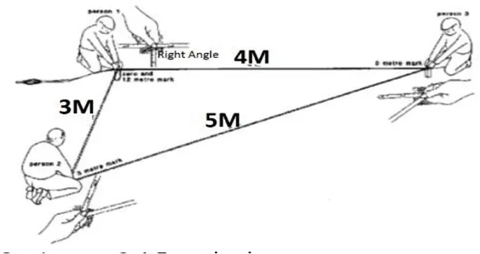
Fig 3: schematic of the 3-4-5 method
3 meters is measured from the parallel line created, then 4 meter away from the first point forming a Right Angle, you use your measuring tape to confirm the distance between the 3m point noted at the parallel line and the 4m noted at the other line is 5m. Note that your parallel line remain the same, you only shift the other line to form the right angle.
You repeat the same process for the Second Point Too.
(vi) Establish your profile
Now we have 4 pins in the ground establishing the outside of our dig. The next thing we need now is to set up our profiles, these should be about 1000mm away from our 4 pins, make sure these extension are all the same and accurate. You make use of your wooden peg in forming all this extensions.
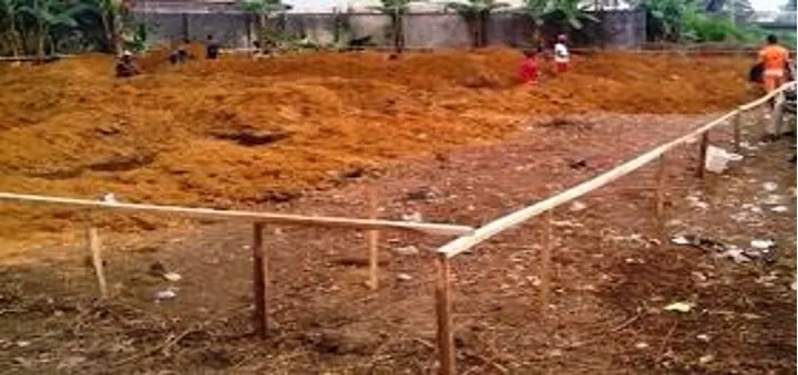
Fig 4: A set out profile on site
(vii) Nail the points of excavation on your profile
Extend and Plumb up your lines and mark the line on top of your profiles and put in a nail and write on the profile something like “outside of dig” from this point we can mark the centre of our dig, which will also be the centre of our structural wall. Put in small nails and repeat this on on each partition of the building.
(viii) Excavation
Excavate the set points to a depth where the ground is firm enough (rock depth or hard murram) or to 1.5m minimum (for the case of red soils) to withstand the loads from the structure. Excavation width should be in such a way that it allows for a working space.
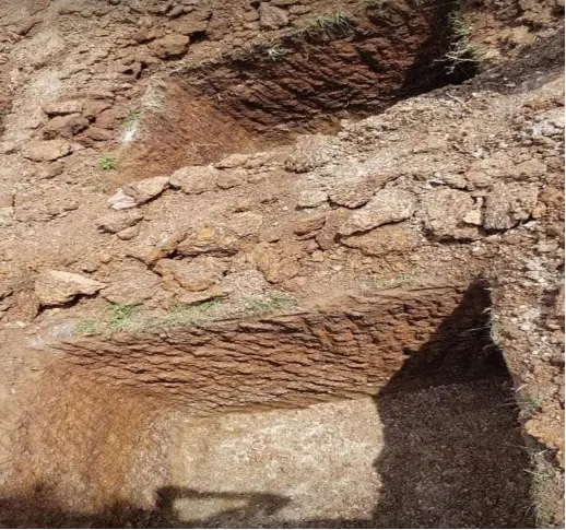
Fig 5: Excavation to firm ground
(ix) Nail the points of column on your profile
When you are done with your excavations, the next thing is to remove your Line and Nail another point to establish our columns. If you are using Out to Out, make sure you use it all through and if you are Using In to In, Use it All through.
Your column placement will be where your lines intercept each other. Make sure you make use of spirit level while placing your columns.
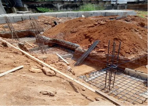
Fig 6: Column placement in reference to the profile
2. Choice of construction materials
A good structure is as good as the materials used for its construction. These materials include murram, hard-core, building stones, steel reinforcement bars, timber, cement, sand and coarse aggregates. It is therefore imperative that good quality materials are used.
Coarse aggregates should be of uniform sizes while sand should be free of any silt and other solid materials.
Hardcore should be of nearly uniform size that is not too big and not small.
Proper concreting is also a very important factor to note during concrete works. Proper water to cement ratio (typically 0.5) should be ensured. The right mix ratios of cement:sand:coarse aggregates should be followed consistently depending on the concrete class require. E.g. mix ratio for class 20 is 1:2:4 while that of class 25 is 1:1.5:3.
Laboratory testing for the construction materials can be carried out to ascertain their strengths. Some of the reputable materials testing laboratories within Nairobi include Central Testing Laboratories (CTL), MassLabs and Surtech Laboratories.
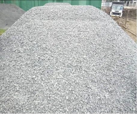
Fig 7: Good quality coarse aggregates
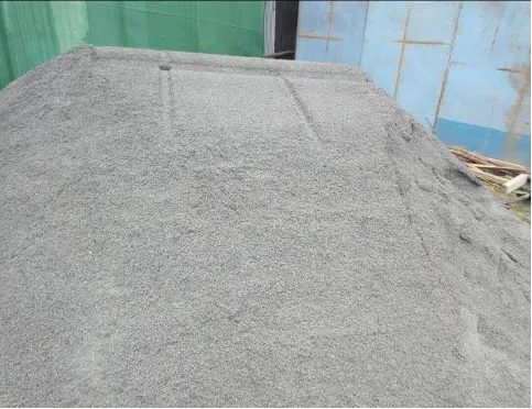
Fig 8: Good quality graded rock sand.
3. Foundation
The foundation of a house is the base on which the building load will be transmitted safely to the ground. Therefore, it is probably the most important determining factor of your home’s future durability and safety. A compromised foundation is among the worst structural problems a homeowner may face.
The foundation of a house must therefore be formidable. In an attempt to minimise their workload, some Kenyan builders may opt to begin construction on unprepared land.
This is dangerous because if the ground is unprepared, then it may not have the capacity to support the structure being raised from it. Before the foundation is laid, an adequate layer of firm topsoil must be put to act as a building pad for the house being constructed.
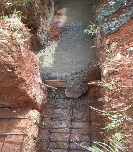
Fig 9: Casting of strip foundation
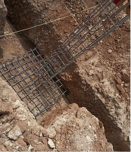
Fig 10: Column base on a firm ground
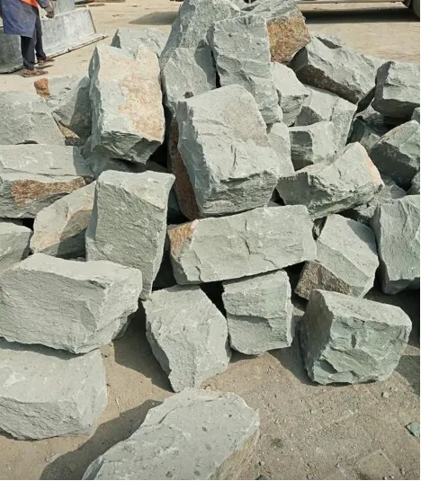
Fig 11: Good quality foundation wall stones
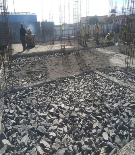
Fig 12: Blinding process with final compaction on-going.
The following points are important to note during the construction of the foundation;
- All excavated sections should be well levelled and a layer of 50mm (2inches) thick. concrete blinding placed. This ensures the levels are true, and adds a concrete cover protection to the reinforcements.
- All foundation walls should be constructed on top of a strip foundation that is reinforced. Typically, these strip foundations are 600mm wide and 250mm in depth, with reinforcement being D10 bars spaced at 200mm apart.
- Natural quarry stones (minimum 200mm thick) should be used for the construction of foundation walls. These stones should have a compressive strength of 14MPA minimum.
- Machine cut stones should never be used for construction of foundation walls. This is because they have high porosity and thus would have ground water penetrating into them weakening these walls.
- All foundation walls should be reinforced with hoop iron after every two alternate courses.
- The thickness of the mortar between the masonry joints should not be more than 25mm (1 inch).
- Proper reinforcement should be placed on all the column bases and columns as per Structural Engineers plans and quality concrete placed and well vibrated.
- Good quality murram should be backfilled and well compacted on all excavated sections within the house plan after all the foundation walls, column bases and columns have been constructed to ground level. This backfilling and compaction should be done in layers not exceeding 150mm (6inches).
- Hard-core should be well handpacked (in layers of 150mm) on top of the backfilled murram layer on which a layer of fine aggregates is placed to fill up any spaces left by the hanpacked hardcore.
- A damp proof membrane (DPM) is placed on top of the blinding, on which BRC A142 is placed in readiness for ground floor slab concreting.
- The thickness of the ground floor slab should be 125mm (5 inches) minimum.
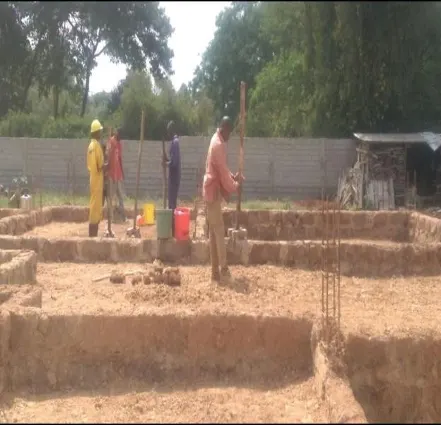
Fig 13: Poor compaction on poor quality murram
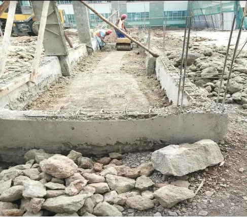
Fig 14: proper compaction on good quality murram
4. Walls and columns
The following key consideration should be noted during construction of walls and columns;
- All walls should be made from quality masonry blocks with a minimum of 7MPA. This ensures they have sufficient capacity to adequately carry the loads from the structure. The blocks should have smooth cut edges and not broken
- The stones used should be minimum 200mm thick for all main walls.
- The thickness of the mortar between the masonry joints should not be more than 25mm (1 inch).
- All walls should be reinforced with hoop iron after every two alternate courses.
- All columns should have dimensions and reinforcement bars as shown in the Structural drawings.
- The plumbness of column formwork should be thoroughly checked to ensure they are perfectly straight.
- Proper vibration of concrete in the columns should be done. Good quality concrete should be ensured at all times.
- Proper curing (with clean water) of all masonry joints and casted columns should be done continuously for at least 14days.
- Links to hold the main column bars should be correctly placed and tied together at spacings shown on the structural drawings.
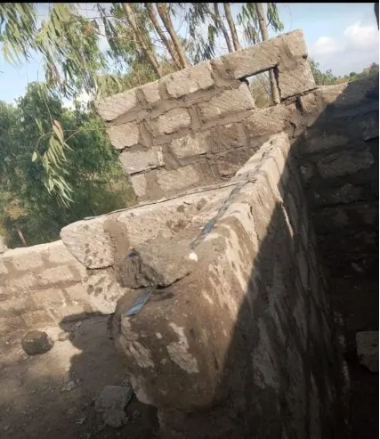
Fig 15: Hoop iron in wall construction
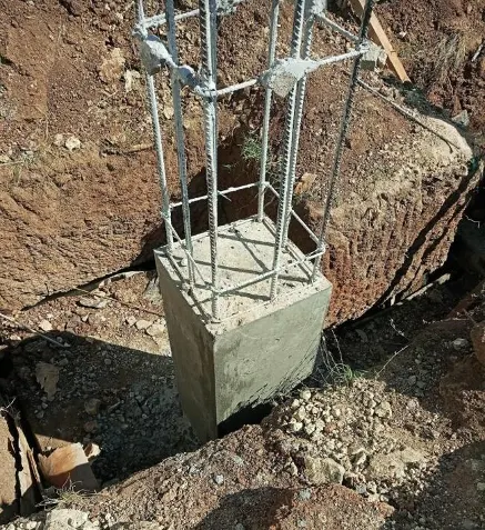
Fig 16: Column reinforcement bars
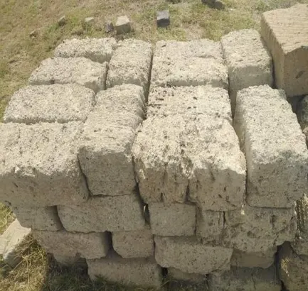
Fig 17: Poor quality stones
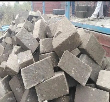
Fig 18: Good quality machine cut stones
Typical link shapes are as shown here below
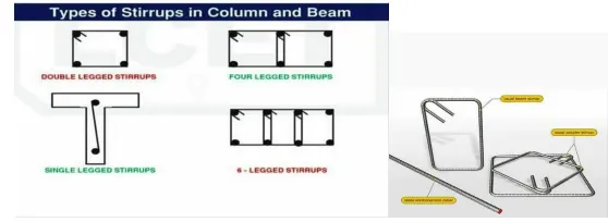
Fig 19: Common links for beams and columns
5. Staircase
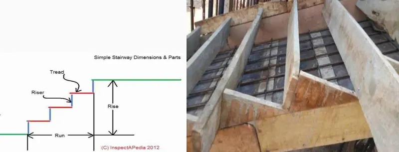
It is important to ensure ergonomical construction for staircases to minimize strain during usage. The risers and treads should be of standard height, typically 150mm for risers and 250mm for treads. Proper reinforment should be placed correctly as per the structural drawings. Starter bars for the staircase should be provided during before casting the ground floor slab.
.
Fig 20: Typical staircase details
6. Floor slab
The first thing to put in place for a suspended floor slab is the formwork. This supports the concrete slab before complete curing takes place. Correct levels should be checked while placing the formwork.
Proper rebars for both the floor beams and the slab should be placed according to the structural drawings. Lap lengths (typically, this is given as 50 times bar diameter) should be provided where bars are to be extended.
Proper uniform spacing for all floor slab reinforcement should be placed in strict conformity with the structural drawings.
Links to hold the main beam rebars should be correctly placed and tied together at spacings shown on the structural drawings. Improper tying of these links may lead to cracking of the whole beam which can have catastrophic consequences. Consequently, the correct rebar size for the beams should be placed and properly tied in place together with the links.
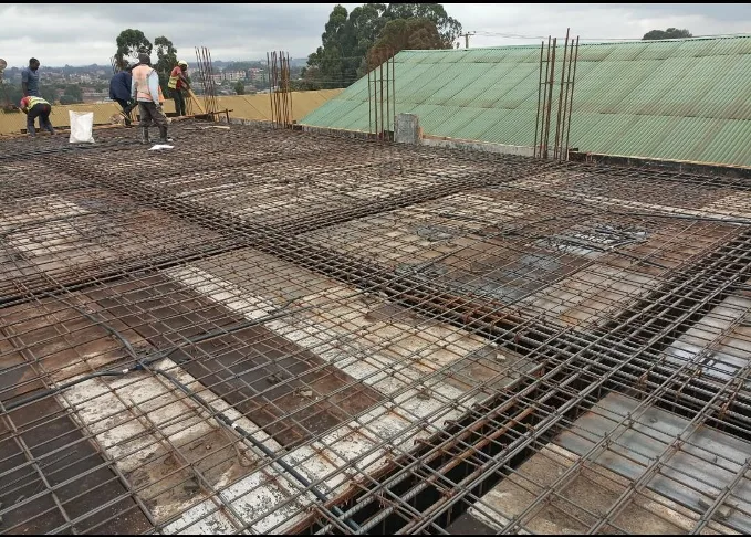
Fig 21: Floor slab and beam reinforcements
7. Roof Trusses/ flat slab
For a pitched roof;
Ø The trusses should be made from good quality timber, free from any defects or rotting.
Ø The correct section sizes for the timber used for the roof should be in accordance with the structural drawings
Ø Spacing of trusses, rafters and purlins should be as per the structural drawings.
Ø All timber used should be properly treated against anti-termite.
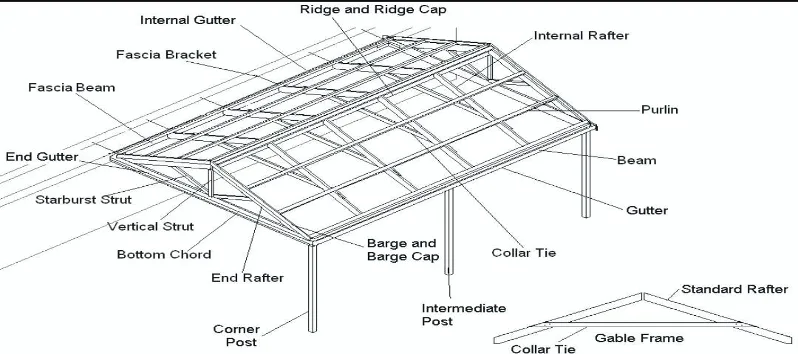
Fig 22: Parts of a pitched roof
For a flat roof, the key factors considered in a normal floor slab should also be considered. Other factors to consider in this include;
Ø Ensuring that the roof slab is properly waterproofed to avoid leakages when it rains.
Ø To have a gentle slope of approximately 2% to ensure that water doesn’t stagnate when it rains.
Ø Gutters and downpipes should be placed for both types of roofs to evacuate the rain water away from the building’s foundation. This helps protect the integrity of the foundation.
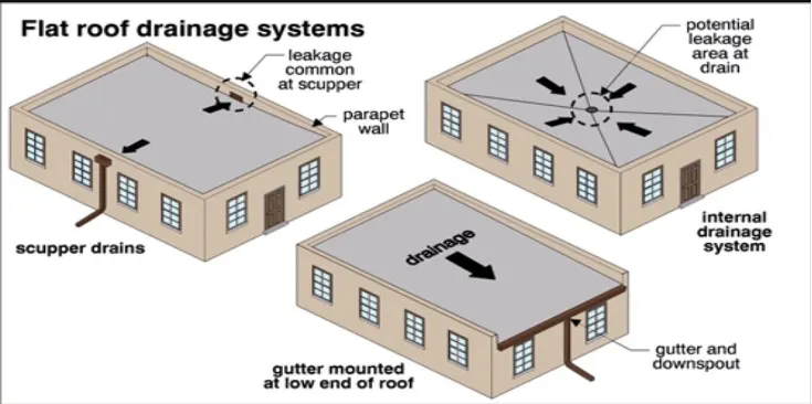
Fig 23: Flat roof systems
Posted Under: